Technological Institute of Aeronautics

São José dos Campos - São Paulo - Brazil

Requirement 5: Cruise speed


 Background

Four physical forces act on an airplane at cruise in level flight (see picture):

    Figure 1: forces actuating on an airplane at cruise

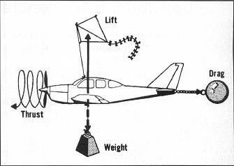
At this condition, the engine thrust (T) must be the same as the drag force (D) and the lift (L) must cancel the weight (W, which is changing because the airplane is burning fuel).

A demanding situation occurs when the aiplane is cruising at MMO (Maximum Operating mach Number) at the service ceiling. This situation is one of those considered for sizing purposes.

 Reason to live

What we know?

  1. Mach mumber at cruise.
  2. Cruise altitude.
  3. Wing aspect ratio.
  4. Maximum takeoff weight, W0.
  5. Wing loading: W0/Sref.

What we must calculate?

  1. T0/W0.

Equations

As explained before, for the cruise condition we have:

T=D and L=W.

However, L and D can be written as

yielding

We must rewrite the above equation in order to obtain the desired T0/W0, where T0 is the maximum thrust at takeoff and W0 is the maximum takeoff weight:

or


A relation for Tcruise/T0 is provided by Prof. Scholz of Hamburg University of Applied Sciences:

where hcruise is the cruise altitude in km and BPR is the engine by-pass ratio.

If we consider the beginning of cruise, the following relation can be derived according to Roskam's suggested values for mass fractions:

Wcruise=0.995*0.98*W0=fW0.

Wonderful! Now he have to estimate the lift-to-drag ratio, i.e., CL/CD.
We start with CL and afterwards proceed with CD estimation.

Considering that both cruise altitude and wing loading are provided, the lift coefficient, CL, can be estimated. We obtain:


The drag coefficient, CD, is something more complex to estimate:


Adopting the Roskam's Class I approach for CD0 estimation,  assuming that CDw is approximately zero , and considering the formula that we already derived for the CL estimation, we obtain:


In the above equation, all parameters are known. Swet can be calculated from MTOW using the following expression:

  Swet is obtained in ft2. W0 must be provided in  lb.   


Now we are able to estimate the required thrust-to-weight ratio for the wing loading that was provided. In fact, we vary the wing loading and insert the corresponding T0/W0 ratios into the design diagram.

 
  Back to the missed approach requirement
  Back to the design diagram

© 2012  Bento Mattos